This system is built to follow a ball on a background using vision and a linux based servo control system.
The project has two major components for the processing and control. On one side we have a processing node that basically operates on a ROS framework. This can be implemented using anything from a Raspberry Pi to a TX2, but due to the lack of financial backing, we decided to just simulate it using a Virtual Linux through Oracle VM VirtualBox. This node is responsible for everything from image processing to angle calculation form the pixel value that is returned after identifying the location of the object.
The second part in the Control Node that is in-charge of controlling the Servos using PWM values. This part is accomplished using a Gumstix Verdex that acts as an intermediate node Between the Processing Node and the Servos.
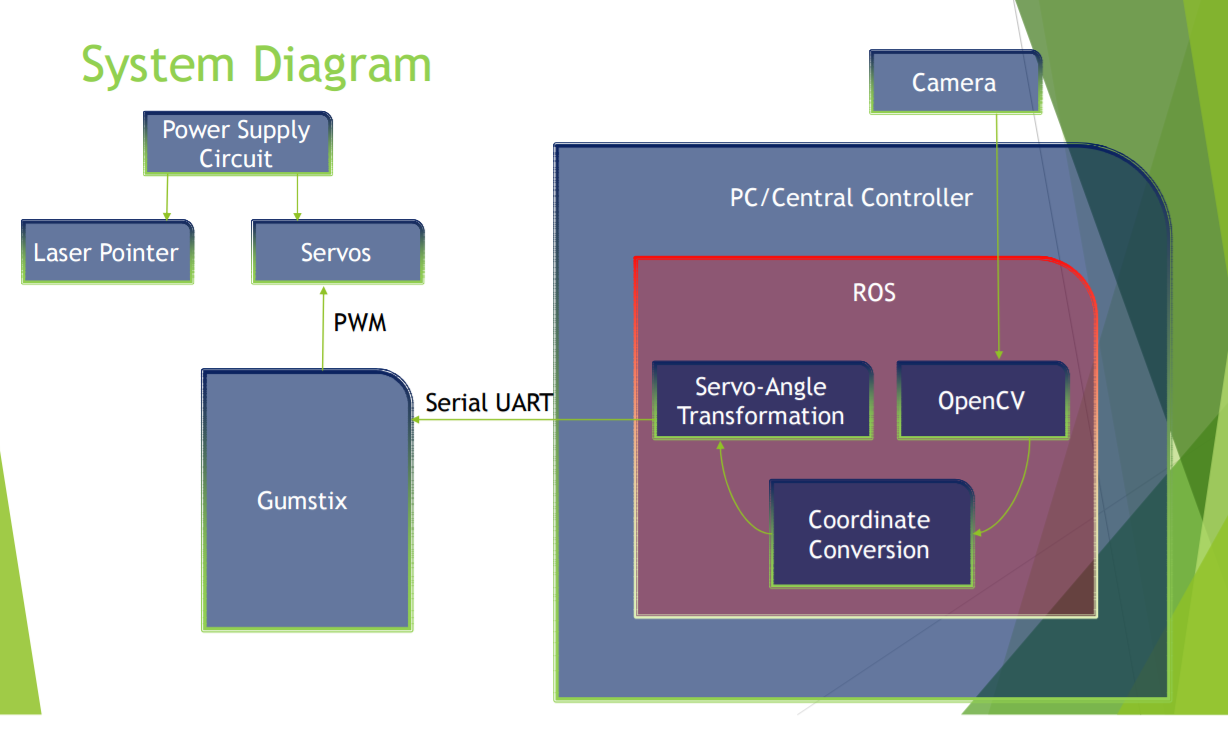
The ROS Node consists of three major nodes (Fig. 3.1) that independently perform tasks and communicate results via ROS Topics. The OpenCV node takes in the output from the camera and processes it by first doing a Gaussian Smoothening the then Hough Circle Transform to discover the location of the black Ping-Pong ball.
After doing that, it sends this location to Coordinate Conversion Node. This node now takes these values that are in pixel location format and scales down the values to 100 to accommodate further conversion. Next it takes these scaled down values to convert to Polar. Then it sends the Polar Coordinate Values to the next node Servo-Angle Transformation.
This node takes the angle value receives and convers it to PWM values that are to be transmitted. These values are then sent as “echo” commands over serial to the Gumstix to written onto the ‘/dev/servo’ file.
The kernel Module ‘servo.ko’ then takes these values and sets them as the PWM output values to pin 16 and 17 that are taken by the servos to change their angle.
Task Partition: - Hardware setup, OpenCV node: - Muhammad Zuhayr Raghib Servo-Angle Transformation node, Coordinate Transformation node, PWM Driver – Akash Mehta Coordinate Transform node: - This node has two major functions: -
- Take the pixel values and scale them down to a range of 90. This is done to make it easier to translate the value to values relative to the Servo Angles, which go from 0 – 90 in the pan servo and 0 – 90 in the tilt servo. This also invert the values since (0, 0) of the camera is at the top left and (0, 0) of the servo is at pixel (343,403).
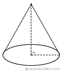
- It then converts these values to polar angles. This is done because the while structure is basically a cone. The peak is where the laser is located and the base is the work area. This also inverts the angle because the (x, y) for the servos correspond to (y, x) for the camera
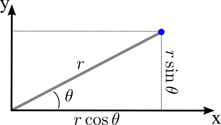 Thus r = (x2 + y2)1/2 and θ = tan-1(y/x)
The Serial Input comes in the form of an ‘echo’ command format. This command takes the PWM values for the pan and tilt in the form of ‘p(value)’ and ‘t(value)’ and redirects them to ‘/dev/servo’ file. Example packet: - echo p500 >/dev/servo echo t500 >/dev/servo
The driver takes the values sent over from the Processing controller via the ‘/dev/servo’ file. It then sets this value as the PWM value for the Servos. These are connected to pin 16 and 17 on the Gumstix Verdex.
If this value is continuously being set, the servo takes a high power consumption, due to which our system would slowly start to become increasingly overexerted, leading in lowering of the Voltage output and steady decline in the holding torque of the servo. To prevent this, the driver would set the PWM values every alternate 20ms cycle. Thus ensuring lower power consumption and a higher holding torque.
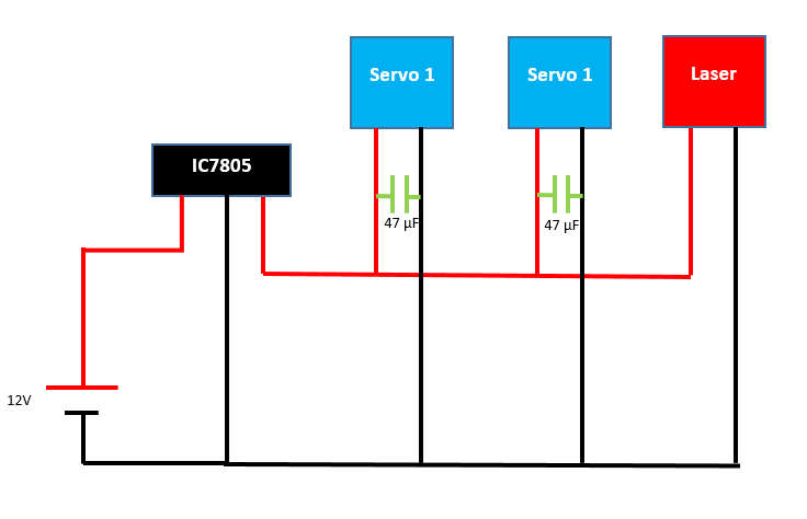
Power Circuit: -
This circuit was powered via a 12V – DC power adapter and regulated using an IC7805. The positive was connected to a switch that further on was sent to the laser and the two servos in a parallel manner. There were 2 - 47µF capacitors connected across the power pins of the servos to further help counter any power fluctuations that might be experienced by the power source